
05/11/2026 11:02:50
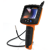
These problems are often not caused by the camera itself, but by less-discussed technical factors such as light reflection, viewing angle limitations, push cable stiffness, and changing conditions inside the pipeline.
These problems are often not caused by the camera itself, but by less-discussed technical factors such as light reflection, viewing angle limitations, push cable stiffness, and changing conditions inside the pipeline.
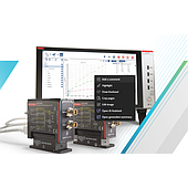
As semiconductor technology shrinks, performance control alone is no longer enough. Manufacturers now need to closely monitor component lifespan and stability from the wafer development stage, because even a small change in material or transistor structure can significantly alter the component's behavior over time
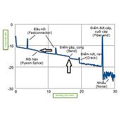
Technicians often view an OTDR fiber optic tester as a device used mainly to locate fiber breaks. Testing is usually performed only after the link loses signal completely or optical loss increases significantly. However, with the rapid growth of FTTH, XGS-PON, and high-speed data centers, many optical networks now experience performance issues even though the OTDR trace does not show any obvious fault.
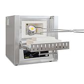
Temperature deviations do not always occur because the target temperature is incorrect. In many cases, the real issue is that the heating rate is incompatible with the thermal characteristics of the material inside the furnace chamber.
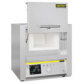
Burned-out heating elements are a common issue in laboratory furnaces, heat-treatment workshops, and high-temperature material processing lines. In many cases, the root cause is not simply the temperature setting itself, but the way heat is distributed inside the furnace chamber.
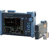
Fiber access networks, data centers, and high-speed transmission systems now operate almost continuously with extremely tight stability requirements. Even a small increase in optical loss can create intermittent instability long before a complete signal failure occurs, making the problem difficult to detect with conventional testing methods.
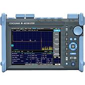
During fiber optic installation and troubleshooting, technicians sometimes encounter a strange situation: the OTDR displays a massive reflection spike indicating a cable break or severe fault, yet when they inspect the reported location, the fiber is completely intact. In some cases, the indicated fault even appears beyond the physical length of the cable itself.
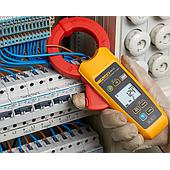
In modern industrial electrical panels, RCCBs or ELCBs are increasingly tripping unexpectedly even when the system appears to be operating normally. In many cases, the issue persists despite using a leakage current clamp meter, performing insulation resistance tests, and even replacing the residual current circuit breaker itself.
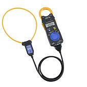
When choosing a clamp meter, most users tend to focus on the measurement range, CAT safety rating, or brand reputation. However, one of the most critical factors affecting measurement quality actually lies in the design of the clamp jaw itself.
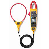
A CAT IV clamp meter does not guarantee absolute safety if the environment contains high transient voltage spikes or if the measurement procedure is not performed correctly. In many cases, the real danger is not the voltage displayed on the screen, but extremely short voltage surges capable of generating arc flash and destroying the instrument within microseconds.
Get exclusive volume discounts, bulk pricing updates, and new product alerts delivered directly to your inbox.
By subscribing, you agree to our Terms of Service and Privacy Policy.
Direct access to our certified experts