How to test the LED Driver using the 3341G Series LED DC Electronic Load Simulator
To comply with the global trend of energy saving and reduce carbon emissions, LED lighting applications are increasingly used in consumer products {such as LED TV, mobile phones, flashlights, etc.), and for general lighting purposes, replacing inefficient incandescent bulbs. Other examples include automotive applications {headlamps, directional lights, brake lights, interior lights, fog lights, instrument lights and so on), public works {LED street lights, traffic lights, etc.) and office lighting (to replace fluorescent). While the use of LED lighting was initially limited to specific applications, it is now widely adopted by the market and attracts massive investments. To be competitive in this growing market and stand out from competitors, not only is the price and quality of the LED’s used important, of equal importance are the supporting devices required, especially the LED driver power supply.

The LED current driver supply must support several combinations of up to dozens of LED, either in series or parallel in actual application in order to achieve the required number of lumens. The supply has to convert AC power into LED DC current. For these power supplies, energy efficiency is an important parameter to maintain overall energy efficiency, low energy consumption and high efficiency LED lamps can reduce the amount of heat losses and also can extend the LED light service life. Efficiency improvement is the goal of any LED drive power design. The current trend in LED driver technology is towards higher voltage applications at higher power levels to reduce overall current. Not only can this improve the efficiency, is also saves cost of copper of materials used in wiring. In addition, in order to further save energy, as well as to allow lighting adjustment to the surrounding environment, dimming of LED lights can achieve further energy-saving. Thus, the LED driver must not only provide a stable DC current source, it must also satisfy the dimming control requirements.
Almost lighting manufacturers are investing heavily in development and production of constant current LED drive power supplies to meet the huge demands of lighting market. As LED prices continue to decrease, they will soon completely replace the incandescent light bulbs causing the market to expand rapidly in the future.
The output of an LED driver has a constant current profile. The output voltage is based on the LED equivalent on voltage Vd and the equivalent series resistance Rd. Unlike a traditional power supply, the output is a fixed voltage which necessitates the use of an LED electronic load to quickly simulate and verify performance and reduce the product development schedule for shorter time to market.
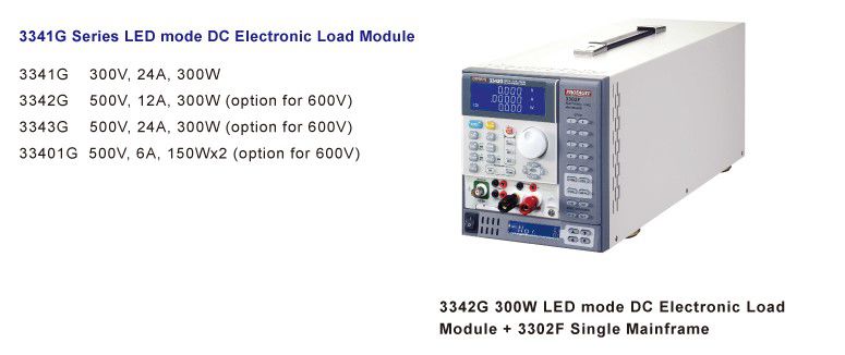
Prodigit introduced 3341G series LED dimmable DC electronic load, including 3341G (300V, 24A, 300WJ, 3342G (500V, 12A, 300W), 3343G (500V, 24A, 300W), 33401G (500V, 6A, 150Wx2), LED drive power for testing and verification. These loads can simulate real LED characteristics, based on LED parameters inputs (including Vd threshold voltage, Rd series resistance, Vo output voltage, etc). Thus, there is no longer any need to connect actual LEDs to the LED drive power supply. It also allows for easy changes in the LED parameters to simulate different number of LEDs in a string, LED specifications or LED brands. It also has the necessary control signal for dimming control of the LED driver, including a 0 to 12V Analog voltage and 0 to 1kHz, 0 to 100% duty cycle output signal which is the best tool to test and verify LED power drivers.
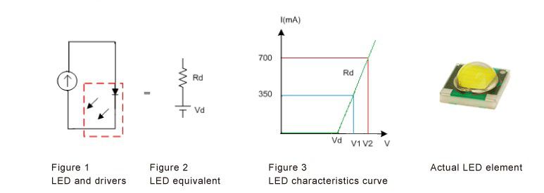
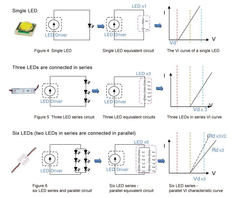
For the actual LED Vd and Rd values and characteristics, refer to the LED manufacturer’s specifications or use the actual test data of the LED components. For the latter approach, change the current values through the LED one by one and record the corresponding LED terminal voltage at each step so you can draw the entire characteristic curve of LED I / V current-voltage.
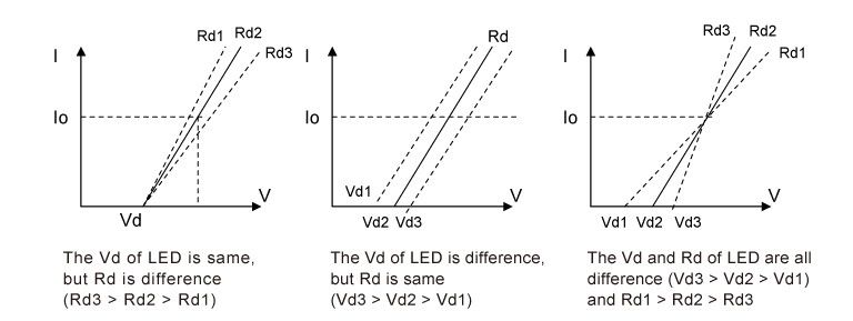
When the lumen output of a single LED is insufficient, you can choose a higher power LED or use multiple LEDs in series. Since multiple LEDs in series can increase the output brightness, multi-unit LED array packaged products are already available. In this case, Vd and Rd will be multiplied by the number of LEDs in series. Figure 4 through 6 show the equivalent circuit and the corresponding characteristic curve for a variety of LED series configurations and their various LED lighting applications:
For LED Driver output voltages higher than 500V, there is a 600V option available when placing the order. For more details please refer to Prodigit 's website or contact Prodigit’ s sales department.
The following sections describe the differences between the LEO mode load and the general electronic load:
The purpose of an LED driver is to convert electricity into LED lighting suitable for driving the light fixture according to the end-user needs. There can be special types and general types of lighting.
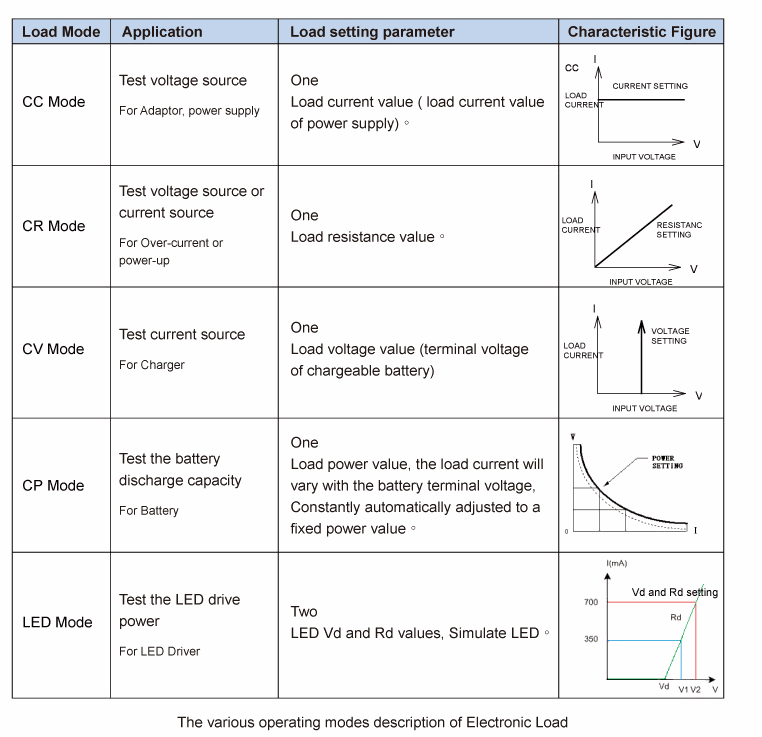
The CR mode of electronic load; only need to set one parameter, setting CR mode and R = Vo / lo, is used as a voltage source or current load, although the CR mode may be used to test LED Driver, but the equivalent circuit is different from the same characteristics as the LED and cannot achieve the effectiveness of LED simulation.
The CV mode of electronic load; only need to set one parameter, setting CV mode and V = Vo are used as the current source of the load, although the CV mode may be used to test the LED Driver, the equivalent circuit is different from the same characteristics as the LED and cannot achieve the effectiveness of LED simulation.
The CV mode of electronic load; only need to set one parameter, setting CV mode and V = Vo are used as the current source of the load, although the CV mode may be used to test the LED Driver, the equivalent circuit is different from the same characteristics as the LED and cannot achieve the effectiveness of LED simulation.
LED mode: LED mode is for the simulation the equivalent circuit diagram Figure 2 of the LED. Integration of the above CR mode + CV mode, 3341G series LED mode must also set two parameters simultaneously, they are Ud and Rd respectively, Figure 14 shows the current waveform and the actual LED load, same as those in Figure 13.
Figure 14 is 3341G LED MODE electronic load voltage Vo and current Io waveform, when the output voltage reaches 25,6V, lo current begin to increase, the same as the LED equivalent circuit.
Config and LED monitor
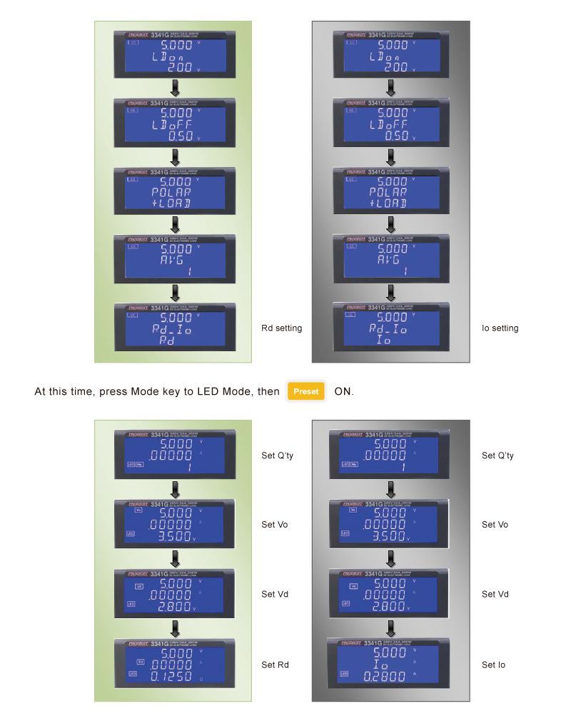

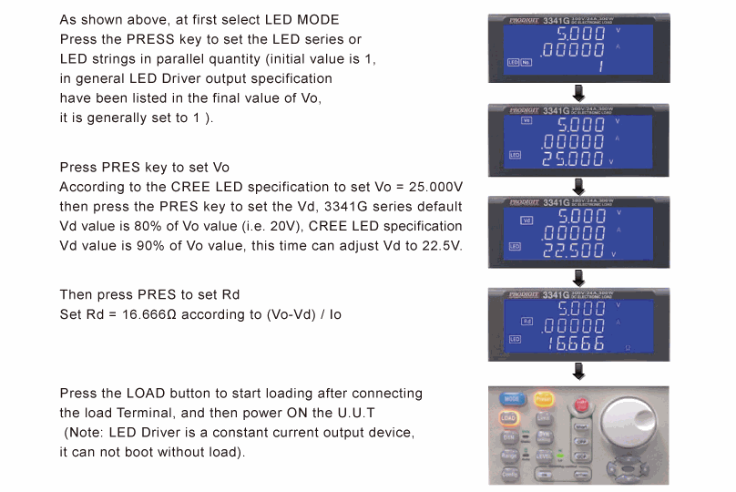 Vo & Io setting and actual output:
3341G series LED mode load requires setting of Vo, lo and Rd so as to simulate the LED characteristics curve Shown in Figure 3, So it is not the actual LED load value.
The LED Driver output is constant current. As such, unlike other voltage sources using the same general electronic load short circuit function, for short-circuit test the short circuit impedance of an electronic load is not low enough. This means the led to LED Driver short-circuit protection cannot be used.
To overcome this, the 3341G series LED mode Load specifically provides a 12V power supply and Short Relay output interface to control the external 12V shorting relay. It also provides an optional short-circuit-specific fixture board. The circuit board can be installed on the corresponding LED load module short-circuit relay, for use with 3341G, 3342G 1 3343G and 33401G three models respectively.
The 3341G series LED load module short output on the panel will drive the installed fixture board of the relay. The relay control of the contact point will cause the load's positive and negative input to short-circuit. This happens directly on the LED Driver s output to provide only a few mOhm of short-circuit resistance. It is used to verify correct operation of the test short circuit protection function
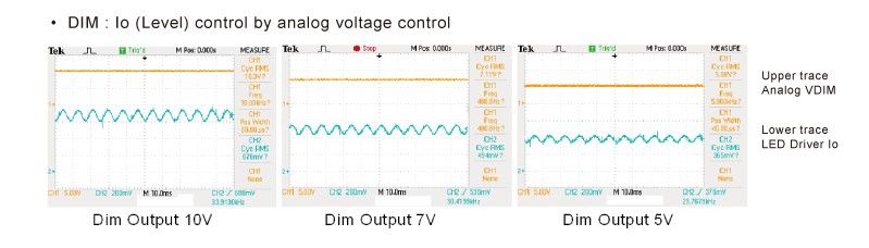
[%end-text-img-same-line%]Next, when the LED Driver has dimming function, Prodigit provides the test solution for the dimming LED Driver dimming device can be divided into TRIAC dimming and Analog/PWM dimming modes.
The dimming test of Analog/PWM dimming mode is to use a set of control signals to the LED Driver's dimming control input to control the LED Driver output current working cycle to achieve LED dimming, the LED Driver verification test must have a set of control signals to do dimming control. 3341G series LED mode Load provides a set of DIM control output voltage signal which is isolated from the electronic load module, adjustable voltage level 0 ~ 12V, Duty Cycle 1- 99%, Frequency DC ~ 1KHz, by using the module to achieve the function of the system that can be simulated 0 - 12V analog dimming voltage signal or digital PWM dimming signal, these can be adjusted and controlled by 3341G series load module, operation is very convenient, when the verification test the dimming capacity of LED Driver, the use of the standard dimming control, you do not need an additional signal generator as the dimming control signal.
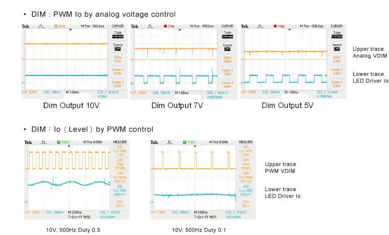
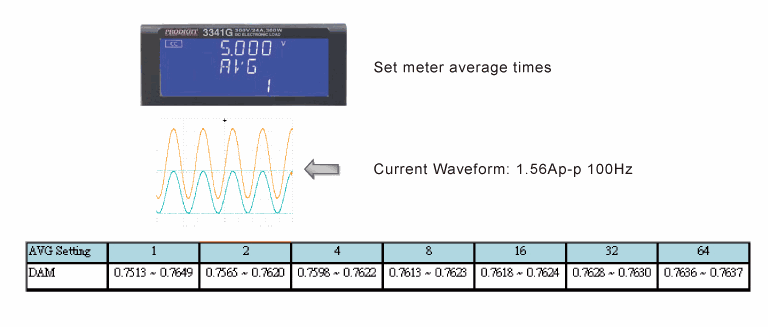
With the implementation of PWM dimming, the LED Driver output voltage and current are variable. This may lead to the meter reading of 3341G series LED electronic load to be not