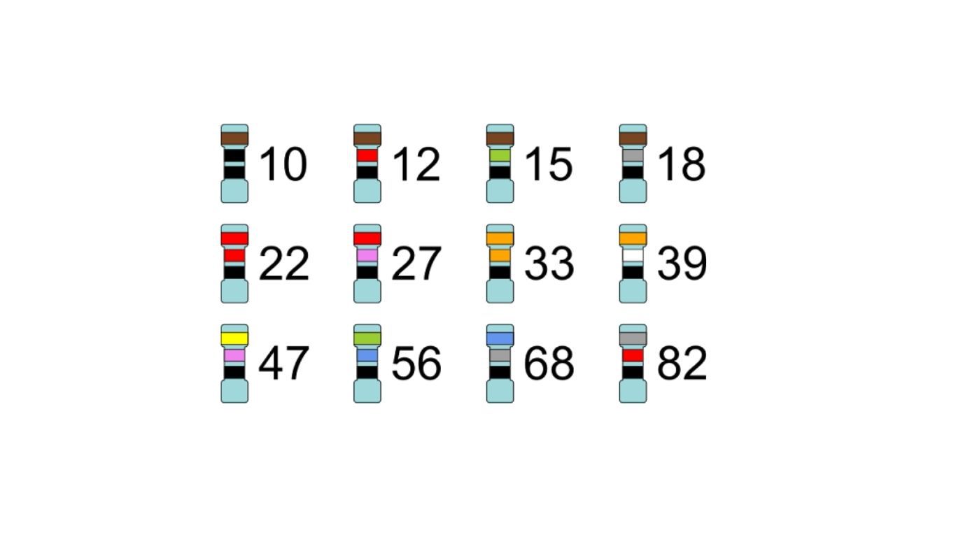
This is not a coincidence. Behind these seemingly odd numbers lies a mathematical principle recognized worldwide. It is known as the E-Series standard - the common “rulebook” that standardizes the global electronic component industry.
What is the E-Series Standard?
The E-Series (Preferred Numbers) is a system of standardized values established by the IEC (International Electrotechnical Commission), specifically under IEC 60063.
Instead of producing every value from 1 to 100, manufacturers focus only on a specific set of values. This system is based on geometric progressions and logarithmic distribution, ensuring that selected values cover the entire range without excessive overlap or gaps.
To simplify circuit design, engineers use standard value tables. These base numbers are then multiplied by powers of 10 (e.g., 4.7, 47, 470, 4700...).
Basic E-Series value table:
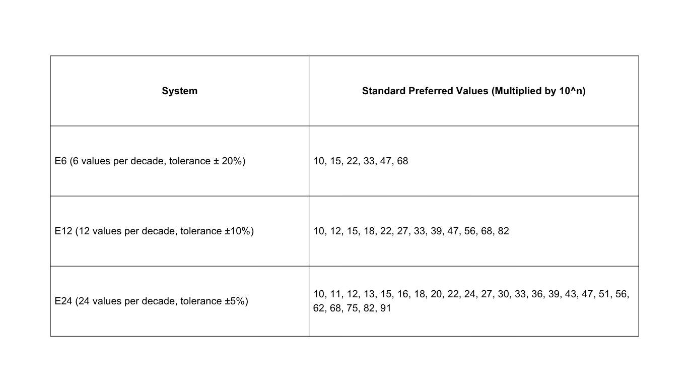
When moving to higher series such as E48, E96, or E192 (used for high-precision resistors), the values become denser and closer to “round numbers,” as tolerances are reduced to below 1%.
Why Don’t Capacitors Have Values Like 15µF or 25µF?
The answer lies in the relationship between standard values and tolerance.
Let’s take the E6 series (±20% tolerance) as an example:
A 10µF capacitor with ±20% tolerance can have an actual value anywhere between 8µF and 12µF.
The next value in the E6 series is 15µF, which ranges from 12µF to 18µF.
As you can see, the upper limit of 10µF (12µF) perfectly meets the lower limit of 15µF (also 12µF). Together, they fully cover the range from 8µF to 18µF without any gaps.
So why not produce 12µF or 14µF capacitors?
If a 12µF capacitor with ±20% tolerance were made, its actual range would be 9.6µF to 14.3µF, which is already completely covered by the existing 10µF and 15µF values.
Similarly, a 25µF capacitor is unnecessary because 22µF and 33µF already cover that range effectively. Producing additional “round” values would be redundant and could even create confusion in component selection.
Rend more: What is the difference between a capacitor and an inductor?
Why Understanding the E-Series Matters in Circuit Design
Understanding standard component values is not just theoretical—it has real economic benefits.
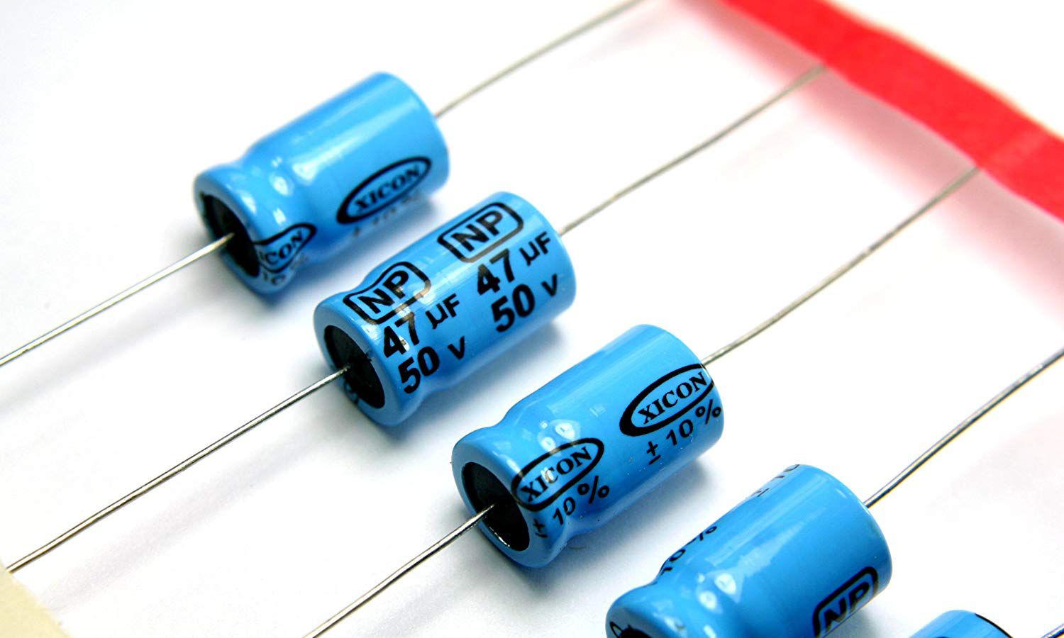
Components in the E12 and E24 series are widely available, easy to source, and much more affordable than uncommon values. Designing circuits using standard values makes it much easier to find replacements when components fail, no matter where you are.
What if your calculation requires exactly 15µF, but you only have access to E6 values like 10µF and 22µF?
No problem—simply connect a 10µF capacitor in parallel with a 4.7µF capacitor. The result is 14.7µF, which is still within acceptable tolerance for most designs.
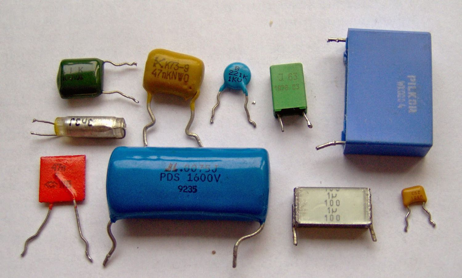
The E-Series system was not created to complicate engineering work—it is a smart solution to standardize the electronics industry. It helps manufacturers optimize production while ensuring users always have accessible components.
When starting a circuit design or calculating component values, always keep an E12/E24 reference table nearby. Choosing standard components is the first step toward a professional, cost-effective, and practical design.