What is a Flow Switch?
Flow switches, also known as flow control switches, are devices used to detect and monitor the presence or flow rate of liquids or gases in pipelines. When the flow rate exceeds or falls below a set value, the switch triggers an ON/OFF signal to a control system such as a PLC, pump control panel, or alarm. Flow switches play a crucial role in flow monitoring, protecting equipment such as pumps, increasing operational efficiency, and ensuring system safety.
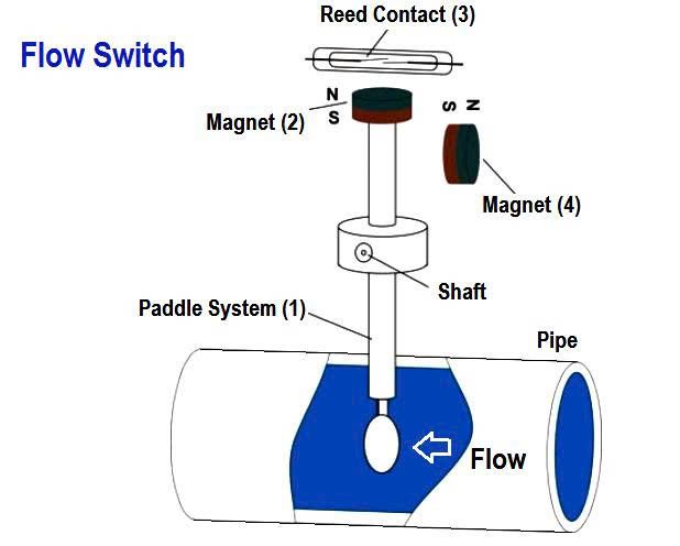
Principle of Operation of Flow Switches
Flow Detection:
The device uses mechanical or electronic sensors to detect the flow of liquids or gases in the pipeline.
ON/OFF Signal:
When the flow rate reaches the set threshold, the switch changes the contact state (closed or open) to send a signal to the controller or other device.
Common Types of Flow Switches
1. Mechanical Flow Switches
Fan-type and piston-type flow switches.
Advantages: Low cost, easy installation.
Disadvantages: Lower accuracy compared to electronic types.
2. Electronic Flow Switches
Uses electronic sensors for more accurate flow detection.
Suitable for highly automated systems, better sensitivity, and less maintenance.
See product catalog at: EMIN Flow Switches
Applications of Flow Switches in Practice
Pump and equipment protection: Flow switches will shut off the pump when there is no fluid flow, preventing dry running and damage.
HVAC and fire protection systems: In HVAC and fire protection systems, water quality monitoring devices trigger alarms when water flows through the sprinkler system.
Applications in production lines and water treatment: Water flow meters; flow rate and velocity monitoring devices for gasoline, oil, chemicals, and wastewater.
Instructions for Wiring a Flow Switch
Before connecting the flow switch, ensure the power supply is off and the fluid valve is turned off.
Step 1: Prepare the installation location
Choose a suitable pipe location (horizontal or vertical).
Ensure the pipe is clean and does not obstruct the flow.
Step 2: Attach the switch to the pipe
Use a T-fitting or threaded connector to attach the switch.
Ensure the arrowhead points in the correct direction of fluid flow.
Step 3: Signal Connection
Connect the NO/NC contacts on the flow control switch to the control system (PLC/electrical cabinet).
Ensure proper connection to accurately ON/OFF the feedback signal.
Step 4: Complete Operation Check of Flow Control Switch
Open the valve, turn on the power, and accurately meter the operating signal according to the flow rate setting.
Benefits of Using Flow Control Switches
Enhance system safety: Monitor appropriate fluid flow, provide protection
Optimized automatic equipment prioritization: PLC linkage, maintenance, control
Reduced operating costs: Avoid equipment damage, increase lifespan
Suitable for many industrial applications: HVAC, water treatment, fire fighting, production lines