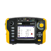
Why does the machine still break down despite regular maintenance?
Many production lines experience rapid bearing degradation, persistent seal leaks, or abnormally high bearing temperatures even when maintenance schedules are fully followed. The cause is often not due to materials but rather to misalignment between the drive shafts.
Mistakes in parallel or angular directions create continuous forcing forces acting on the couplings and bearings. These forces do not appear instantaneously but accumulate over time, causing the components to wear out faster than originally designed.
Common symptoms include significantly increased vibration under load, noise generated in the drive area, and heat concentration at bearings or seals. At the system level, power consumption increases because the motor has to compensate for energy loss due to misalignment.
Causes of shaft misalignment
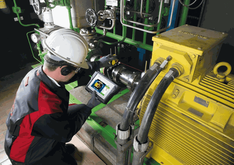
Shaft misalignment rarely stems from a single factor. In fact, many systems are affected by causes often overlooked during installation and operation.
Soft bases can deform the chassis when bolts are tightened, causing the shaft to shift from its initial measured position. Pipe stress also creates constant tensile forces, particularly in pump and compressor systems. As operating temperatures rise, thermal expansion alters the geometry of the entire assembly if not compensated for from the outset.
In addition, torque generated during machine start-up or stop-up can cause shaft displacement. Small errors from manual measurements, if repeated many times, will accumulate into a large misalignment that the operator may not notice.
An effective approach to axis alignment.
Traditional methods are still valuable in simple systems; however, they rely heavily on operator experience and are difficult to control errors in complex field conditions.
Laser solutions offer a more intuitive approach. Measurement data is displayed during alignment, allowing technicians to monitor changes in real time and make precise adjustments at the machine's base. For systems with vertical flanges, large measurement distances, or limited space, laser technology demonstrates a clear advantage.
By incorporating vibration and thermal imaging data, the overall condition of the machine is more fully understood. This allows for alignment that goes beyond axial geometry and is closely linked to the actual operating conditions of the equipment.
Refer now: Concentricity alignment machine, pulleys, belts
Quick answers for field technicians
1. How often should the concentricity be checked?
At least once a year or after major overhauls. For machines operating continuously, under high load, or playing a critical role in the production line, the inspection cycle should be shortened to minimize the risk of unplanned downtime.
2. Is the dial gauge still suitable?
This method is still used in many factories, however, it requires high skill and a lot of time. In environments requiring precise data and accuracy, laser equipment reduces reliance on intuition and increases the repeatability of results.
3. The machine still vibrates even after alignment
The foundation, base, and piping system need to be checked. If these factors have not been thoroughly addressed, the concentricity achieved during measurement will quickly change once the machine is put into operation.